Inside the Teletype Mechanism · Volume 1
Inside the Teletype Mechanism — Vol 1: How Iron Reads a Bit
A Model 15 has no clock, no memory, and no electronics. It decodes a serial data stream with a magnet, five cams, five swords, and a gear ratio of eight to seven — and that last number is the cleverest thing in the machine.
1.1 The question I could not answer as a boy
I sat in my father’s shack and watched the teletypes run, and for years I had no idea what was actually happening inside them. I knew the pattern — a burst of chatter, the carriage flying back, the bell — and I knew it was somehow reading the signal coming out of the receiver. But how? There was nothing in there that could think. Just oiled iron, turning.
It took me until I was well into adulthood, and had a service manual open in front of me, to understand what I had been looking at, and the answer is better than anything I had imagined. A Teletype Model 15 performs, entirely in metal, every function a modern UART performs in silicon. It detects a start bit. It recovers timing. It samples five data bits at the correct instants. It latches them into a register. It decodes that register into one of dozens of actions. It resynchronises on every single character so that errors cannot accumulate.
It does all of this with a magnet, a shaft, some cams, and a set of pivoted levers named — I am not making this up — swords.
This volume is the receiving path: how a stream of current-and-no-current becomes a decision about which letter to print. Volume 2 is the other half — how that decision becomes ink on paper.
1.2 The signal it has to read
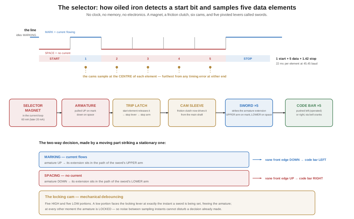
From Teletype Machines and RTTY on the Air: the code is the start-stop five-unit code. Each character is a frame:
- 1 start element — always spacing (no current)
- 5 data elements — each marking (current) or spacing (no current)
- 1 stop element — always marking, and 1.42 units long on a 60-speed machine
At 45.45 baud each unit is 22 milliseconds long. The line idles marking — current flowing continuously — so the machine is holding a steady current whenever nothing is happening. This matters practically: an open line looks like a permanent space, which is why a disconnected machine begins hammering away at a blank character. That is “running open,” and it is the first thing a Teletype will do to you when you power it up unconnected.
Marking is current, spacing is no current. Hold onto that, because every mechanical action below follows from it.
1.3 The magnet, the latch, and the start
The selector magnet is the machine’s only sensor. Its coils sit in the line’s current loop — 60 mA on the classic machines, 20 mA on later ones — and the armature is pulled up whenever current flows.
While the line idles marking, the armature is held up, and a small chain of parts holds the entire receiving mechanism motionless: the stop arm, part of the selector cam sleeve, is engaged against the stop lever, which is in turn held by the trip latch. The main shaft is turning — the motor never stops — but the selector cam sleeve is held still against a friction clutch, slipping quietly, waiting.
Then a character arrives, and its first element is the start element: spacing, no current. The magnet lets go. And a sequence of small mechanical events follows in a few milliseconds:
- The armature spring pulls the armature away from the pole pieces.
- That motion drives the trip latch plunger.
- Which moves a bell crank.
- Which pulls the trip latch out of engagement with the stop lever.
- Which releases the stop arm.
- And the friction clutch, which has been slipping all this time, now drives the selector cam sleeve around with the main shaft.
The machine has detected a start bit. It did it with a spring and a latch, and the whole point of the start element is that it is always spacing — a guaranteed, unmistakable transition from the idle state that can only mean “a character is beginning now.”
1.4 Five cams, five swords, five bits
Now the cam sleeve is turning, once per character, and on it are cams positioned to fall at the centre of each of the five data elements. Sampling in the middle of each element, not at its edge, is exactly what a UART does and for exactly the same reason: it is the point furthest from any timing error at either end.
Each of the five bits is read by a chain of four parts — a selector cam, a selector lever, a sword, and a T-lever — which together set one vane. The mechanism is a two-way decision made by a moving part striking a stationary one, and which one it strikes depends on where the armature is at that instant:
- If the element is marking, current is flowing, the armature is pulled up, and the upper end of the armature extension sits in the path of the sword’s upper arm. The cam rotates the selector lever, the sword strikes the upper end, and pivots one way.
- If the element is spacing, no current, the armature is down, and the lower end of the extension sits in the path of the sword’s lower arm. The sword strikes there instead, and pivots the other way.
Either way, when the cam clears the selector lever, the lever’s spring drives the sword against the T-lever, which brings the corresponding vane either front-edge-down (marking) or front-edge-up (spacing). Through a set of bell cranks, each vane pushes its code bar left (operated) or right (unoperated).
At the end of five elements, five code bars are lying in a pattern that physically encodes the character. That is the register. It is made of steel and it holds its state because the bars are simply sitting there in the position the swords put them.
The mechanism can only be wrong in one place at a time. A locking cam with five high and five low portions on its rim runs alongside. A locking lever, spring-loaded against it, drops into a low portion at exactly the instant a sword is being set — freeing the armature to move — and is pushed up into a high portion at every other moment, locking the armature. The consequence is that noise on the line between sampling instants cannot disturb a decision that has already been made. It is mechanical debouncing, and it is the reason the machine can copy a signal that is not perfectly clean.
1.5 The eight-to-seven trick
Here is the part I find genuinely beautiful, and it is the answer to a problem I had never thought to ask about.
Two teletype machines, potentially thousands of miles apart, must agree on when each element begins. They have no shared clock — that is the entire point of an asynchronous start-stop system. Each has its own motor, and no two motors run at exactly the same speed. Even a tiny difference accumulates: a machine running 0.5% fast drifts a whole element’s width in twenty characters, and after that it is decoding garbage.
The engineers’ answer is a gear ratio. The selector cam sleeve is geared to rotate one-seventh faster than the transmitting cam shaft. Not the same speed — deliberately, precisely, 8:7.
The geometry compensates in the same proportion, so the timing still lines up. Where the transmitting keyboard’s cam shaft must travel 48½° to get from sending one impulse to sending the next, the receiving selector cam sleeve travels 55½° between the corresponding sampling points — one-seventh further, at one-seventh the speed advantage, arriving at exactly the same moment.
And then the payoff. Because the receiver runs fast, it always finishes its revolution before the next character arrives, and then it stops and waits — latched by the stop arm again, motionless, until the next start element trips it. The manual puts it about as clearly as it can be put:
“If the speed of the selector cam sleeve is slightly faster than its proper speed, the only effect will be that it will remain at rest slightly longer. If its speed is slightly slower than the proper speed, it will remain at rest just that much less time … due to the fact that the selector cam sleeve starts each revolution in unison with the transmitting cam shaft this error does not become any greater.”
The timing error is reset to zero at every single character. Speed differences produce a slightly longer or shorter pause between characters and nothing else — they never accumulate. The stop element exists precisely to guarantee there is room for that pause.
This is, functionally, clock recovery. It is the same job the phase-locked loop in a modern receiver does, and it is being done here by making one shaft turn one-seventh faster than another and letting it wait. There is no clock in a Teletype. There is a gear ratio and a latch, and between them they solve the problem completely.
1.6 Orientation: taking a range
The 8:7 ratio guarantees the receiver starts in step. It does not guarantee it samples at the best instant within each element — that depends on the line, the distortion it introduces, and the machine’s own adjustment. So the Model 15 has a way to slide the sampling point, and it is called orientation, or taking a range.
On the stop lever plate — part of the range finder assembly — sit the stop pawl and the stop pawl latch, and the whole plate can be rotated. Rotating it changes the relationship between where the selector cam sleeve starts and when its cams operate the selector levers. In effect, it shifts every sampling instant earlier or later within the element. A graduated scale shows the setting, and a clamping screw locks it.
The procedure is the reason the phrase is “taking a range” rather than “setting the range finder.” You feed the machine a continuous stream of test text and then:
- Move the range finder down until the machine starts printing errors. Note that number — the lower limit.
- Move it up until errors begin again. Note that — the upper limit.
- Set it in the middle.
The width of that error-free span is the range, and it is the single most useful diagnostic number a teletype gives you. A healthy machine on a clean line has a wide range — many tens of points. A narrow range means something is wrong: a weak or misadjusted selector magnet, a dirty or sticking mechanism, a distorted signal, a wrong loop current, a speed error. The range tells you not just how to set the machine but how healthy it is, which is why it is the first measurement in any restoration and the last check after any adjustment. It comes back in Restoring a Teletype, Vol 2, where it is the acceptance test.
Volume 2 takes the five code bars sitting in their pattern and turns them into a letter on paper.
1.6.1 Sources (Vol 1)
- 🔴 Primary source: Teletype Corporation / Bell System Practices, Description of Teletype Model 15 Teletypewriter, Section P70.013 — the selector magnet, armature and armature extension; the trip latch plunger → bell crank → trip latch → stop lever → stop arm release chain; the selector cam sleeve on the left end of the main shaft driven through a friction clutch; the selector cam / selector lever / sword / “T” lever / vane / bell crank / code bar chain and its marking-vs-spacing behaviour; the locking cam with “five low and five high portions”; the 8:7 synchronism argument with the 48½° and 55½° figures and the quoted passage on why the error does not accumulate; and the range finding mechanism on the stop lever plate with its graduated scale and clamping plate screw. Retrieved from the US Navy Radio Communications documentation archive. https://navy-radio.com/manuals/tty/p70.013-iss1-5110.pdf ⟨the live host 403s automated fetches; the identical PDF is served by the Internet Archive’s raw mirror⟩
- Selector magnet electrical characteristics — 60 mA classic loop current (20 mA on later machines), and the coil’s very high inductance. Trammell Hudson, “Model 15 Teletype.” https://trmm.net/Model_15_Teletype/
- Start-stop frame structure (1 start + 5 data + 1.42 stop at 45.45 baud) — see Teletype, Tape & RTTY → Teletype Machines, which cites the code-lineage sources.
- “Running open” — a machine not connected to a loop reads a permanent spacing condition and strikes blanks repeatedly. David Stickelman, “Getting started with a teletype.” http://stickelman.net/index.php/2025/02/23/getting-started-with-a-teletype-my-consolidated-notes-on-restoration/
- Cross-links: Teletype Machines (the code and the model lineage); Restoring a Teletype (taking a range as a health measurement); Wireless Modes → The Shift-Keying Family (the same start-stop framing seen as modulation).