Paper Tape and the Perforator · Volume 1
Paper Tape & the Perforator — Vol 1: The Pink Tape
The reels of punched paper tape spooling out of my father's teletypes are my sharpest memory of that room. Here is what those little rows of holes actually said — and how you read them with nothing but your eyes.
1.1 The pink tape
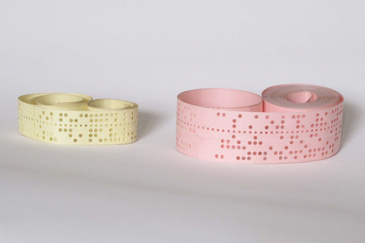
Of everything in my father’s shack, the thing my hands remember best is the paper tape. It came spooling out of the punch in long pale ribbons, curling into the wastebasket, covered in neat little rows of holes — and in my memory it is pink. (I’ve since learned teletype paper and tape came in yellow, buff, blue, and yes, pink; the color is real, even if the pink is partly a boy’s memory.) I would pick up a length of it and hold it to the light and know there was a message in those holes, if only I could read it. This dive is where I finally learned to — and where I get to show you. Punched paper tape is one of the most beautiful ideas in the whole history of communication: a message you can hold in your hand, read with your eyes, store on a shelf, and feed back into a machine years later.
1.2 What punched tape is
A teletype speaks in five-bit characters (the Teletype Machines dive covers the ITA2 code). Punched tape simply writes those five bits onto paper as holes: a hole is a 1 (mark); no hole is a 0 (space). Each character is one column of holes straight across the width of the tape, and the tape’s length is just one character after another. Punch the tape as you type, and you’ve recorded your message in a form that never forgets, never mistimes, and can be sent perfectly by a machine long after you’ve walked away. It is the teletype’s memory, made of paper.
1.3 Reading it by hand
You really can read tape with your bare eyes once you know two things: the layout and the code. Figure 1 is a strip of real 5-level tape, and it genuinely spells a word.
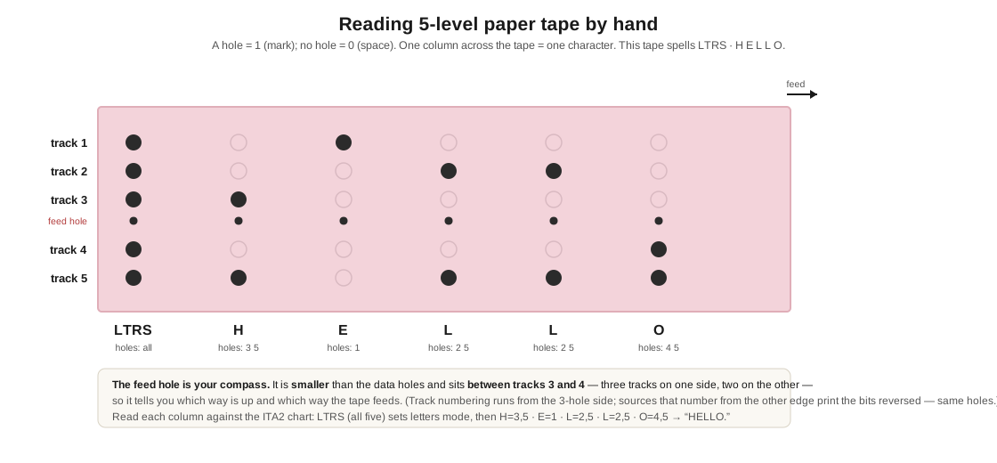
Here’s the whole method:
- Five data tracks run the length of the tape, one bit each. A punched hole in a track = a 1; no hole = a 0.
- The feed hole is your compass. Between the tracks runs a line of smaller holes — the sprocket/feed holes that a toothed wheel grips to pull the tape along. It is off-centre: there are two code tracks on one side and three on the other. That deliberate 2-vs-3 asymmetry, plus the feed hole being smaller, tells you at a glance which edge of the tape is which, and so which hole is which level.
- Read each column against the ITA2 code. In the figure: the first column has all five holes punched — that’s the LTRS shift character, setting the machine to letters. Then H (levels 3, 5), E (level 1), L (levels 2, 5), L again, and O (levels 4, 5): H-E-L-L-O.
1.4 Between 2 and 3, or between 3 and 4?
Look the layout up and you will find two answers. A US Navy training chart of the five-unit code labels its tape 1 2, feed hole, 3 4 5: the feed holes run between levels 2 and 3 (Commons, File:Baudot.jpg; reproduced in Interfacing Teletypes and Paper Tape, Vol 5). Other references, among them the deramp.com Teletype code document cited below, say the feed hole sits between tracks 3 and 4. Both are right. They describe the same tape and the same holes. They count from opposite edges.

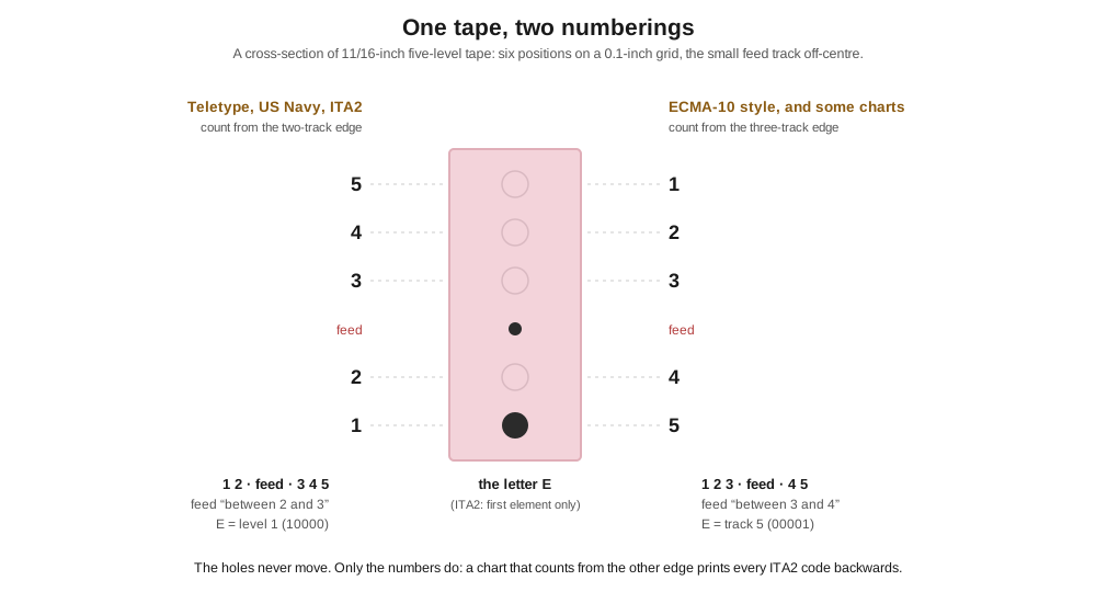
Because the feed track is off-centre, the tape has a two-track edge and a three-track edge, and “track 1” depends on which edge you start from:
- Teletype and the Navy count from the two-track edge. Level 1 is the outer hole on the narrow side, level 2 is next to it, then comes the feed track, then levels 3, 4 and 5 out to the far edge. The level numbers are the same as the order of the five code elements on the line: level 1 is the first element sent after the start pulse. That is why ITA2 charts give E as “1” (a single hole) and A as “1 2”: on a real tape, E is the hole on the outside of the two-track side, and A is both holes on that side. This is the numbering to use with any Baudot chart and with any Teletype manual.
- ECMA-10 counts from the three-track edge. The European standard for punched tape (ECMA-10, 1965) defines a reference edge as “that with three data tracks between it and the feed hole track”, and numbers the tracks from it: track 1 is nearest the reference edge, so the feed track falls between 3 and 4 (ECMA-10, §2.2.1 and §3.2; Library copy). On one-inch, eight-level tape that is the natural choice, and ASCII machines such as the Model 33 put bit 1 there. Apply the same rule to five-level tape, as some charts and descriptions do, and the count starts at the other edge from Teletype’s: Teletype’s level 1 becomes “track 5”, and the feed track is “between 3 and 4”.
The practical consequence is in the bit strings. A chart that counts from the three-track edge prints every ITA2 code reversed: E becomes 00001 instead of 10000. Nothing on the tape has changed. Before trusting a printed code table, check which edge it calls 1. The easy test is E. If the chart calls E’s single hole 1, it uses Teletype numbering; if it calls it 5, it counts from the three-track edge. This dive, the Model 15 and Model 28 dives and Interfacing Teletypes and Paper Tape all use the Teletype numbering, 1 2 · feed · 3 4 5.
Which way round is a tape? The off-centre feed track settles one question and leaves another open:
- Which edge is which. Find the side of the feed holes with only two code tracks. That is levels 1 and 2. The other three are levels 3, 4 and 5. A fully punched tape looks the same from either face, so this is all the holes themselves can tell you.
- Which end is the start. Turning a tape over and swinging it end for end puts the two-track edge back where it was, with the characters in reverse order. The holes cannot distinguish the two. Other evidence can: the printed characters along a typing reperforator’s tape read correctly only one way; chadless tape’s half-punched flaps lie on one face; ECMA-10 asks for tapes to be “marked, or the ends cut, to give a positive indication of the direction of forward tape movement” (§3.5); a leader usually begins with blank tape and then LTRS. Failing all of those, read a few characters both ways. Only one direction spells words.
1.5 Five-level and eight-level
There are two tapes you’ll meet, and telling them apart is easy:
- 5-level (Baudot/ITA2) tape — the classic teletype tape, 11/16 inch wide, five data tracks, feed hole off-centre between levels 2 and 3 (Teletype numbering). This is the tape of the old 5-bit machines (Model 15, 19, 28) and the pink ribbons of my memory.
- 8-level (ASCII) tape — 1 inch wide, eight data tracks, from the ASCII machines (the Model 33 and early computers). Wider tape, more holes per column — an easy visual tell.
(There was even a 6-level tape for typesetting, 7/8 inch — but 5 and 8 are the ones you’ll actually see.)
1.6 What the tape was made of
The tape itself is a small material history. Ordinary paper tape was cheapest and came, as I remember, in colors — yellow, buff, blue, pink; oiled paper tape ran more smoothly through the punches and readers (at the cost of gummy chad). And for heavy or repeated use there was Mylar (polyester) tape — a tough, thin plastic film, sometimes aluminized so an optical reader could see the holes, sometimes laminated paper-Mylar-paper for strength — the tape you’d use for a program or a message you’d send a thousand times without it wearing out. Volume 2 is about the machines that punched it and read it — the perforator, the reperforator, the transmitter-distributor — and the wonderful torn-tape relay system that ran whole message networks by literally ripping the tape off one machine and feeding it into another.
1.6.1 Sources (Vol 1)
- Wikipedia, “Punched tape” — hole = mark / no hole = space; 5-level tape 11/16 in and 8-level tape 1 in; the smaller, offset sprocket hole dividing the tape into unequal widths; oiled paper and Mylar/polyester tape. https://en.wikipedia.org/wiki/Punched_tape
- 5-level layout (feed hole off-centre, two code tracks on one side and three on the other; data holes 0.072 in / feed holes 0.046 in; 0.1 in pitch; 11/16 in width): deramp.com Teletype Baudot codes doc; Codes & Ciphers (Colossus) tape description. ITA2 letter/hole patterns (E, H, L, O, LTRS) verified across the PRC68 ITA2 guide, Wikipedia “Baudot code,” and UNB ee4253 — with the explicit note that track numbering (and thus printed bit strings) reverses between sources for the identical physical tape.
- Teletype/Navy numbering (1 2 · feed · 3 4 5; E = level 1, A = levels 1 and 2): US Navy Radioman training chart of the five-unit start-stop code, Wikimedia Commons
File:Baudot.jpg, https://commons.wikimedia.org/wiki/File:Baudot.jpg . ECMA-10 numbering (reference edge = the edge with three data tracks between it and the feed track; track 1 nearest it; feed between tracks 3 and 4; 17.46 mm tape allowed for five-track use; direction-of-movement marking): ECMA-10, Standard for Data Interchange on Punched Tape, 1st ed., November 1965, §§2.2.1, 3.2, 3.3.5, 3.5, https://ecma-international.org/wp-content/uploads/ECMA-10_1st_edition_november_1965.pdf (transcription: https://polyomino.org.uk/computer/ECMA-10/; Library copy). - Tape colors including pink and Mylar: circuitousroot.com Teletype supplies; vintage-teletype-paper vendor evidence (pink/yellow/blue). ⟨color evidence is vendor/collector-sourced, stronger for printer paper than punch tape specifically — hedged accordingly⟩