How a Signal Carries Information · Volume 1
How a Signal Carries Information — Vol 1: There Is Only the Sine Wave
Radio has exactly one thing to work with, and it is featureless on purpose. Everything in this sub-project is a different answer to the same question: what do you do to a bare sine wave to make it mean something?
1.1 The whistle that means nothing
Tune an HF receiver slowly across 20 metres some afternoon and you will hear the whole argument of this sub-project inside of a minute. There is a steady unwavering whistle that never changes — somebody’s unmodulated carrier, probably a beacon or a rig left keyed. There is a warble that trades between two notes. There is a sound like a vacuum cleaner. There is a voice that seems to be talking through a comb until you flip a switch and it snaps into a person. There is a chirping fifteen seconds long that stops dead, waits, and chirps again.
Every one of those is the same physical thing — a sine wave arriving at your antenna. What separates them is entirely what somebody did to that sine wave before it left theirs. Hams call the answers modes. This sub-project is about all of them, and it starts here, with the boring one: the steady whistle that means nothing at all.
That whistle is the honest baseline. A perfect continuous sine wave carries zero information. It is the same now as it was a second ago and as it will be a second from now, and a signal that never surprises you cannot tell you anything. Claude Shannon made that precise in 1948, but you do not need the mathematics to feel it — sit and listen to an unmodulated carrier for thirty seconds and the pointlessness is visceral. Everything that follows in this sub-project is a scheme for making a sine wave surprising in a controlled way.
1.2 Three knobs and no more
A sine wave has exactly three things you can grab hold of. Write it the way the textbooks do:
s(t) = A · sin(φ)        where   φ = 2πft + θ
       ▲        ▲                    ▲    ▲
       │        │                    │    └─ θ  phase   (where in the cycle)
       │        └── the angle        └────── f  frequency (cycles per second)
└─────────── A amplitude (how big)- A — amplitude. How big it is. The height of the wave.
- f — frequency. How many complete cycles happen each second, in hertz. Its reciprocal is the period T, the time one cycle takes — nanoseconds up in the GHz, milliseconds down in the audio range.
- θ — phase. Where in the cycle you are at a given instant. Each cycle is divided into 360 degrees, exactly like a circle (or 2π radians, same thing in different units).
That is the whole toolkit. Three knobs. Amplitude, frequency, phase — and as we will see in The Shift-Keying Family, the history of radio modes is essentially the story of people working out how to grab each of those three knobs in turn, and then how to grab two at once.
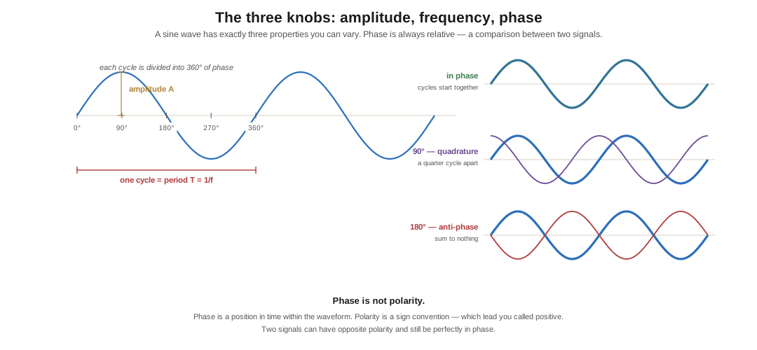
Phase is the one that gives people trouble, because it is the only one of the three that has no meaning on its own. Amplitude and frequency you can measure with one signal in front of you. Phase is always relative — a comparison between two signals, or between a signal and a reference you have agreed to keep. Two sine waves of the same frequency that begin their cycles at the same moment are in phase. Start one a quarter-cycle later and they are 90° apart, in quadrature — a word that will matter enormously by the time we get to QPSK. Start one a half-cycle later and they are 180° apart, anti-phase: both cross zero at the same instants, but heading in opposite directions, and if you add them together you get silence.
Phase is not polarity. This is worth nailing down early because the two words get used interchangeably by people who should know better, and Ward Silver was right to flag it in the seed article for this sub-project. Phase is a position in time within a repeating waveform. Polarity is a sign convention — which end of a battery you called positive, which way round you wired a speaker. Two signals can be of opposite polarity and still be perfectly in phase. And in AC power work “phase” means something different again: one of the distinct voltage waveforms a three-phase utility generates. Three meanings, one word. Say which one you mean.
1.3 Where “radio frequency” starts
A sine wave becomes a radio frequency signal, by convention, once it is above the range we can hear — call it 20 kHz and be done with it. Human hearing tops out somewhere around 20 kHz in a young person with undamaged ears and falls off steadily from there; I am under no illusions about where mine tops out now. The line is a working definition and not a law of physics, and there is plenty of real communication below it: submarines are talked to at VLF, down in the tens of kilohertz, on antennas measured in miles.
Above that line the spectrum runs up through hundreds of gigahertz. The part hobbyists actually live in is roughly 1 MHz to 10 GHz — the AM broadcast band at the bottom, the HF ham bands that this whole project has been circling, VHF and UHF where the repeaters and the handhelds are, and the microwave bands at the top where a dish starts to make sense.
1.4 Modulation is the round trip
Here is the problem, stated plainly. The information you want to send — a voice, a file, a string of Morse characters — is at the wrong frequency to be radiated. A 300 Hz audio tone has a wavelength of about a thousand kilometres. You are not going to build that antenna. Meanwhile a sine wave at 14 MHz radiates beautifully off a wire you can string between two trees, and will bounce off the ionosphere and come down in New Zealand, but by itself it says nothing.
Modulation is the trade that fixes this: take the information, use it to vary one of the carrier’s three properties, and let the carrier do the travelling. Demodulation is the return trip — measure how the received carrier is varying, and reconstruct what caused it. That pair of words is where modem comes from, modulator–demodulator, and I still find it slightly delightful that the box that connected me to a bulletin board in 1988 was named for the same operation that puts my voice on 40 metres.
The information itself is often called the baseband signal, and the carrier is the ride. Every single mode in this sub-project — AM, SSB, FM, RTTY, PSK31, FT8, the D-STAR repeater down the road — is a specific, named, agreed-upon answer to which property do we vary, by how much, and according to what rules.
1.5 Why we draw it in the frequency domain
There is one more thing to establish before we can look at any actual mode, and it is a way of seeing rather than a fact.
Put a modulated RF signal on an oscilloscope and you will be disappointed. The ‘scope shows you amplitude against time, which is the honest physical truth, but the carrier and the information are separated by several orders of magnitude — a 14 MHz carrier being modulated by a 1 kHz tone is fourteen thousand carrier cycles per cycle of the thing you actually care about. Zoom out far enough to see the tone and the carrier is a solid blur. Zoom in far enough to see the carrier and the tone has not visibly moved.
So we change axes. In the frequency domain, amplitude is still vertical, but the horizontal axis is frequency instead of time. This is what a spectrum analyser shows you, and it is what the waterfall on every piece of modern digital-mode software shows you, and once you start thinking in it you cannot go back.
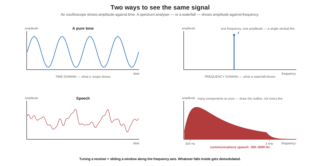
In this view an unmodulated carrier is a single vertical line at one frequency: one frequency, one amplitude, nothing else. That is the whole picture of the steady whistle. Speech is not a line but a shape — a great many components at once, strongest down around 300 Hz and tapering off by 3 kHz, which is why communications gear the world over has settled on 300–3000 Hz as “voice.” You could in principle draw a separate vertical line for every component in a human voice, but nobody does; you draw the outline and everyone knows what you mean.
Tuning a receiver, in this picture, is sliding a window along the horizontal axis. Whatever falls inside the window gets demodulated. That is the entire mental model, and it explains an enormous amount at once — why a narrow CW filter helps, why two SSB stations 2 kHz apart do not interfere, why an FM signal is a fat block you cannot squeeze into a narrow filter, and why a hundred PSK31 signals fit in the space of one voice conversation.
Volume 2 takes this from physics to practice: what a mode actually is (there is more to it than modulation), how the FCC writes them down in its own precise shorthand, and the rule change in 2024 that quietly rewrote what American hams are allowed to invent.
1.5.1 Sources (Vol 1)
- H. Ward Silver, N0AX, “Wireless Modes — Part 1,” Nuts & Volts, March 2017 — the seed article for this sub-project: RF signal basics, amplitude/frequency/phase, the phase-vs-polarity distinction, modulation/demodulation and the origin of “modem,” and the frequency-domain argument. https://www.nutsvolts.com/magazine/article/March2017_HamsWirelessWorkbench_Wireless-Modes
- ARRL, Radio Technology Portal — Radio Technology Topics, for the standard treatment of modulation and the frequency domain. https://www.arrl.org/tech-portal
- C. E. Shannon, “A Mathematical Theory of Communication,” Bell System Technical Journal, 1948 — the formal statement that a perfectly predictable signal carries no information.
- The 300–3000 Hz communications-speech convention is near-universal in commercial and amateur practice; see any ARRL Handbook chapter on speech processing. ⟨the exact endpoints vary slightly by service — 300–3400 Hz is the telephony figure⟩
- Cross-links: The Shift-Keying Family (the three knobs, grabbed one at a time), AM, SSB & the Voice Modes (amplitude), FM & Angle Modulation (frequency and phase).