Interfacing Teletypes and Paper Tape · Volume 2
Interfacing Teletypes and Paper Tape — Vol 2: Loop Supplies, Old and New
The station rectifiers and Navy supplies the machines were built for, the hobbyist's transformer-and-resistor supply, spark suppression on the contacts, and a complete modern design: 48 volts, a MOSFET current sink and a clamp, worked through value by value and brought up on the bench.
2.1 What a loop supply has to do
Vol 1 reduced the loop to physics. A loop supply turns that physics into a specification, and it is worth writing the specification down before looking at any circuit, old or new:
- Deliver the design current — 60 mA or 20 mA — on a steady mark, and hold it there whatever is in the loop.
- Have enough compliance voltage to deliver that current through every magnet, keyboard and wire in series.
- Pull the magnet in fast on each space-to-mark transition.
- Let it go just as fast on each mark-to-space transition, without an arc or a destroyed transistor.
- Keep make and break symmetrical, so that the receiver sees no bias (Vol 1).
- Be isolated from the mains, and from anything else it connects to.
- Be measurable and adjustable, with a meter or a meter jack and a way to set the current.
- Fail safe: fused, enclosed, and not able to hurt the person working on the machine.
Every design in this volume and the next meets some of these and trades away others.
2.2 The supplies the machines were built for
In service, a teletype rarely had a supply of its own. It drew loop current from the office, the exchange or the ship’s communication centre, and those supplies were substantial pieces of equipment.
Bell System station rectifiers. Teletype’s 1964 wiring-diagram section for “rectifiers for teletypewriter station apparatus” shows a family of them, and the typical one is instructive. It is built around a ferroresonant transformer, a constant-voltage transformer that holds its output against mains variation, feeding a rectifier stack and a 1250 µF filter capacitor. Its output is marked 75/120/130 V DC at 0.20 A, and the installer was told to move a tap if the output “exceeds 135 volts under load” or is “below 125 volts under load”. Two hundred milliamperes is three and a bit 60 mA loops.
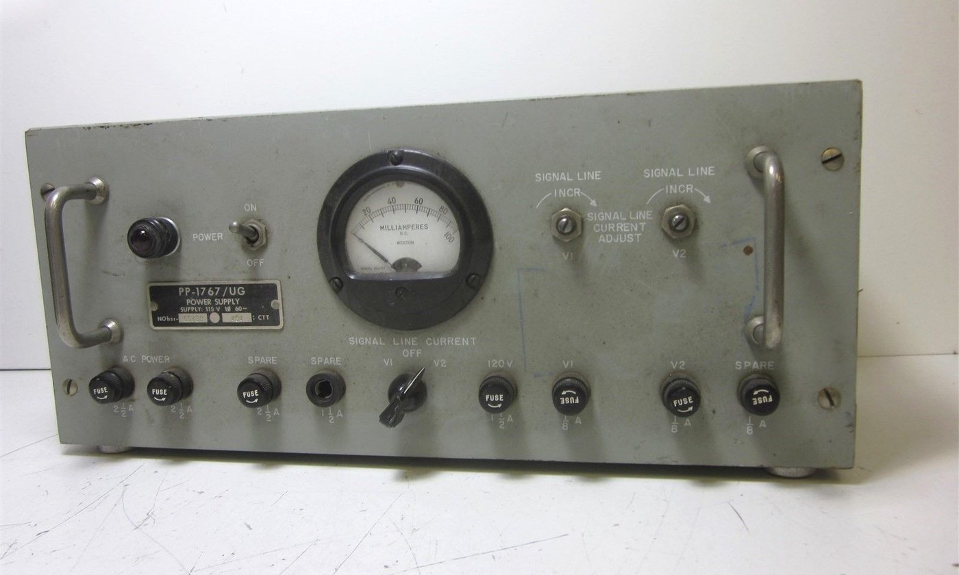
US Navy loop supplies. The Navy’s equipment shows the same ideas at a larger scale. A PP-610/U supplied 120 V DC at 125 mA. A PP-424/U was rated 200 mA, and the Navy’s description of the TT-23/SG teletype panel it fed spells out the arithmetic: “each loop requires 60 milliamperes for efficient operation”, so four loops drawing current at once overload it. The PP-1767 series, used in the AN/SGA-3 crypto system, supplied 120 V DC at 1 A plus two separate 33 V, 60 mA outputs, with magnetic-amplifier regulation in the later versions. The later PP-3494A/UG offered a regulated 48 V or 120 V DC at 0.4 A.
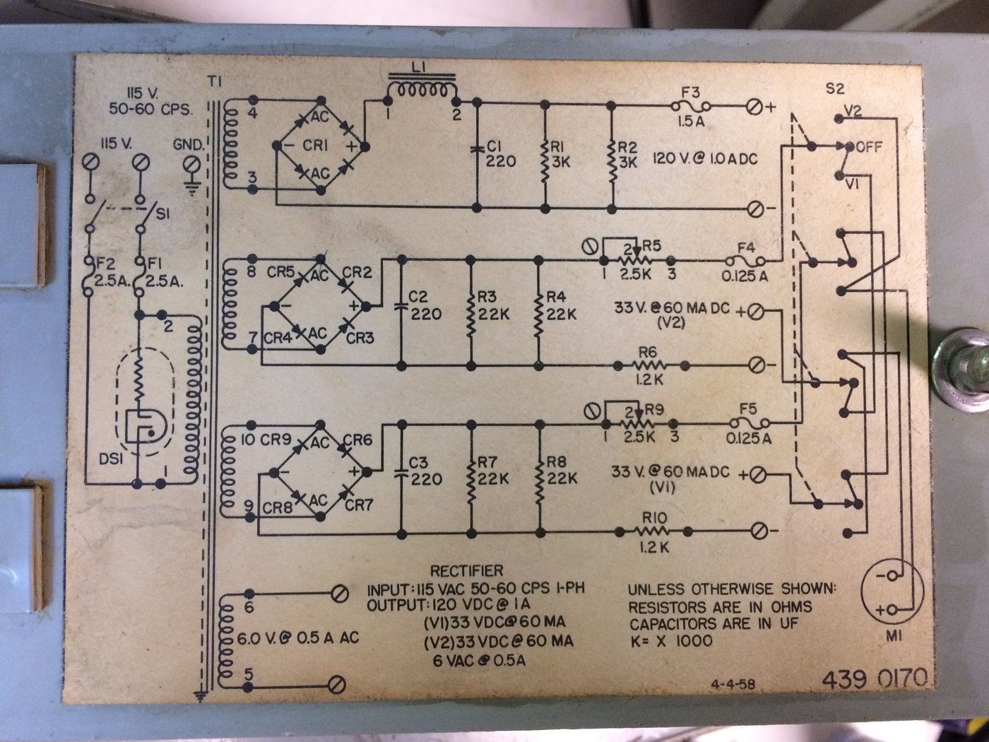
That circuit plate is the classic loop supply in one picture: a transformer for isolation, a bridge, a capacitor, bleeder resistors, an adjustable resistance, and a meter switched between the outputs. It is also a reminder that the Navy saw no need for 120 V on every circuit. The two 60 mA outputs run at 33 volts.
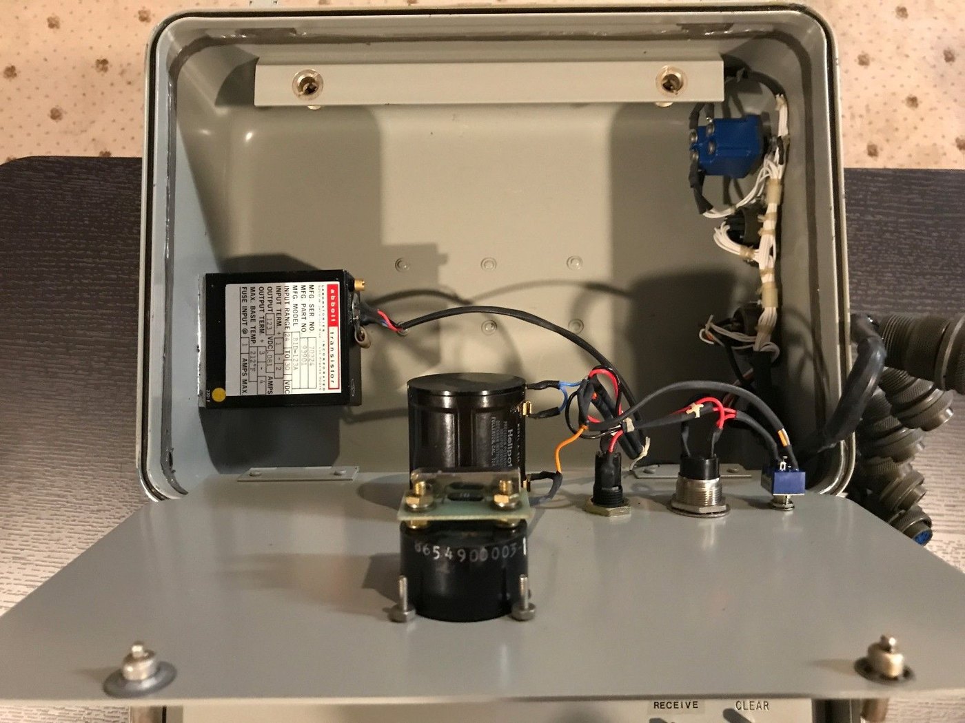
Terminal units. Amateur stations usually took their loop current from the terminal unit. The HAL ST-6 and ST-5000 both contain “a 175 volt, 60 ma. loop power supply”. The ST-6 manual records a running change that tells its own story about heat: “The 2500 ohm loop pot is no longer available. A fixed, 2750 ohm, 20 watt resistor is supplied that replaces both the loop pot” and its companion. At 60 mA, 2750 Ω dissipates
P = 0.060^2 x 2750 = 9.9 Winside the terminal unit, continuously, whenever the loop is idle. The ST-5000 keys that loop with a single 2N5655 high-voltage switching transistor driven from the slicer.
2.3 The hobbyist’s classic
For most of the history of amateur RTTY, a home-built loop supply followed the shape of those station rectifiers, scaled down to one loop:
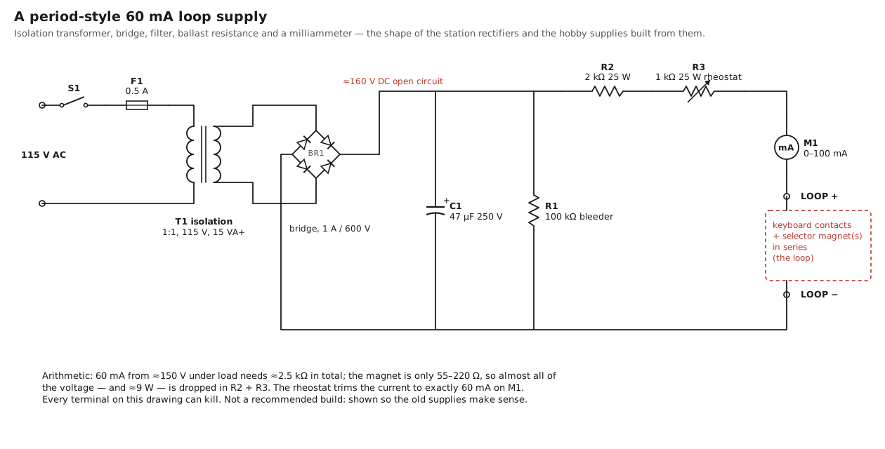
The design choices are each a response to one of the requirements above.
- The isolation transformer (1:1, 115 V) separates the loop from the mains, so that neither side of the loop is tied to the neutral or the earth. Without it, one terminal of the loop is at mains potential.
- The bridge and capacitor turn about 115 V RMS into about 160 V DC unloaded. A 47 µF capacitor ripples by about
0.060 / (120 × 47 µF) ≈ 11 Vpeak to peak at 60 mA, so the voltage under load is about 150 V. The ripple barely matters, because the resistor turns it into a 6 per cent current ripple that the magnet’s inductance smooths further. - The ballast resistance is the current-setting element. A 2 kΩ fixed resistor plus a 1 kΩ rheostat covers 48 to 73 mA from 150 V into a 55 Ω magnet. It dissipates about 9 watts, and it needs a 25 W rating and free air. Those resistors, and the rheostat, are the parts that get hot.
- The meter reads the current directly. The operator sets 60 mA on a steady mark and checks it again after the resistor has warmed up.
- The bleeder discharges the capacitor when the supply is switched off.
Some builders used an incandescent lamp in place of part of the ballast resistance. A lamp filament’s resistance rises steeply with temperature, so it behaves as a crude current regulator: if the loop resistance falls, the current rises, the filament heats and its resistance rises to oppose it. It also makes the loop current visible from across the room. The price is a slow, nonlinear response and a component whose cold resistance is a fraction of its hot resistance, so the current overshoots at switch-on. It is a period trick, worth knowing when a lamp turns up in an old supply, but there is no reason to copy it.
What the classic supply does well is requirement 3: the 2.5 kΩ in series gives the 2 ms time constant of Vol 1. What it does badly is everything else. It runs at a voltage that can kill, wastes nearly all its power, and leaves requirement 4, the release, to whatever opens the circuit.
2.4 Spark suppression on the contacts
Every time a keyboard or transmitter-distributor contact opens a 60 mA inductive loop, the magnet’s stored energy tries to keep the current flowing. With nothing else to absorb it, the voltage across the opening contact rises until the air breaks down, and the contact arcs. The arc erodes the contacts, pits them and builds up oxide, and it radiates.
Teletype treated the radio-frequency part as a problem in its own right. A 1957 Bell System installation section describes the TP97301 filter unit for line relay contacts of Model 14 teletypewriters and typing reperforators, whose function is “to suppress radio frequency induction from the line relay contacts of these machines”. The kit is a filter assembly, a replacement resistor and two screws, wired across the relay contacts. In a radio shack, where the teleprinter sits a few feet from a receiver, the same interference shows up as clicks on every character.
The general remedies are the same today:
- An RC snubber across the contacts, typically around 100 Ω in series with 0.1 µF, rated for the loop voltage. The capacitor absorbs the first rush of current when the contact opens, slows the voltage rise until the gap is wide enough not to arc, and the resistor limits the discharge current when the contact closes again.
- A clamp across the coil. This attacks the cause rather than the symptom. If the magnet’s energy has its own path, a diode and a zener in series across the coil, then the current circulates in the coil and the clamp when the loop opens, and the contacts only ever see the supply voltage plus the clamp voltage, with very little energy behind it.
- Never a plain diode across the coil. Vol 1 shows why: the magnet then releases with its own 73 ms time constant, and it misses the next element.
The two modern designs, Design A below and Design B in Vol 3, use the clamp at the coil, or its energy-recovering equivalent, as the main measure, and keep a small RC snubber across the keyboard contacts for whatever stray inductance remains.
2.5 Design A: a 48 V constant-current loop supply
The Navy’s two 33-volt outputs and Teletype’s own 40-volt selector-magnet driver (Vol 1) point to the design. If the current is set by an active current regulator instead of a resistor, the supply voltage no longer has to be high enough to make the time constant short. A current regulator looks to the coil like a very large resistance, so the full supply voltage appears across the coil during the rise, and the current ramps up as fast as V/L allows. Then the regulator holds it at 60 mA. Add a clamp that lets the current down at the same rate it went up, and the make and the break are mirror images.
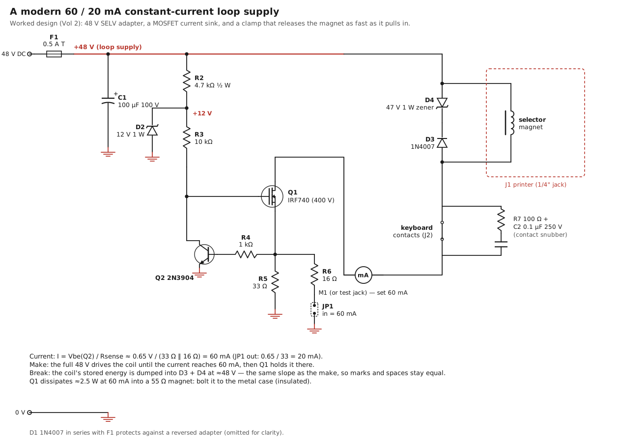
Supply voltage: 48 V. A desktop adapter of the kind sold for network equipment, such as a Mean Well GST25A48-P1J (48 V, 0.52 A, 25 W). It is isolated from the mains by its own construction, it is current-limited, and it is under the 60 V DC level that touch-safe equipment standards use (Vol 1). With 4 H to drive, the current rises at
dI/dt = V / L = 48 V / 4 H = 12 A/s -> 0 to 60 mA in about 5 ms, through 30 mA at about 2.5 msThat is slower than a 120 V resistor loop reaches its half-current point (about 1.4 ms in Vol 1’s simulation) but, as the next paragraph shows, it can be made symmetrical, and symmetry is what the receiver needs.
The current sink: Q1, Q2, R5, R6. Q1 is an N-channel MOSFET in series with the loop, on its negative side. Its gate is pulled up to a 12 V rail through R3, so it turns on hard until the current through the sense resistor at its source develops about 0.65 V. At that point Q2 turns on and pulls the gate down just enough to hold the current there:
I = Vbe(Q2) / Rsense
20 mA:  Rsense = R5           = 33 ohm            -> 0.65 / 33   = 19.7 mA
60 mA:  Rsense = R5 || R6     = 33 || 16 = 10.8 ohm -> 0.65 / 10.8 = 60.3 mA   (JP1 fitted)
R4, 1 kΩ, protects Q2’s base. The two-transistor current limiter is decades old; its virtue here is that it has no reference to drift and nothing to adjust. Its weakness is temperature: Vbe falls by about 2 mV per °C, so if Q2 warms by 30 °C, the current falls by about 9 per cent. Keep Q2 away from Q1’s heatsink. For a tighter current, replace Q2 with a TLV431 shunt reference (1.24 V) and scale the sense resistor accordingly.
The gate rail: R2 and D2. A 4.7 kΩ resistor from 48 V into a 12 V, 1 W zener gives a 12 V rail at about 7.7 mA, enough to pull up the gate through R3 with plenty to spare, and well inside the IRF740’s ±20 V gate rating. R2 dissipates 0.28 W; a half-watt part is enough.
Compliance. The sink needs about 2 V across Q1 and 0.65 V across the sense resistor to regulate. The largest loop it can drive at full current is therefore
60 mA:  (48 − 2.7) V / 0.060 A = 755 ohm of magnets, keyboards and wire
20 mA:  (48 − 2.7) V / 0.020 A = 2265 ohm
That is a holding magnet (55 Ω) or a pulling magnet (about 220 Ω) with plenty of room for a keyboard and a second machine in series.
Dissipation in Q1. Whatever voltage the loop does not use, Q1 burns:
Table 1 — Dissipation in Q1. Whatever voltage the loop does not use, Q1 burns
| Load in the loop | Voltage across Q1 at 60 mA | Q1 dissipation |
|---|---|---|
| 55 Ω holding magnet | 48 − 3.3 − 0.65 ≈ 44 V | ≈ 2.6 W |
| 220 Ω pulling magnet | 48 − 13.2 − 0.65 ≈ 34 V | ≈ 2.0 W |
| two 55 Ω machines in series | ≈ 41 V | ≈ 2.4 W |
| any loop at 20 mA | ≤ 47 V | ≤ 0.95 W |
Two and a half watts is a quarter of what the ST-6’s resistor burned, but it still needs a heatsink. A TO-220 MOSFET bolted to the wall of a die-cast aluminium box through an insulating pad, such as a Hammond 1590BB with a Boyd 4880SG kit, runs a few tens of degrees above ambient. The tab is the drain and sits at loop potential: always use the insulator. For anything larger, a linear regulator is the wrong tool; the DeRamp board’s regenerative switching approach (Vol 3; Making the Parts That No Longer Exist, Vol 2) removes the dissipation altogether.
The clamp: D3 and D4. A 1N4007 and a 47 V, 1 W zener (1N4756A) in series across the selector magnet, the diode’s anode at the end of the coil that goes to Q1. When the loop opens, the coil’s current continues around the coil, the diode and the zener, and the coil sees about −48 V across it. That is almost exactly the +48 V that drove the rise, so the current falls at the same rate it rose. Vol 1’s simulation gives the result: 2.60 ms to cross the half-current level on the make, 2.38 ms on the break, a bias of about −1 per cent. The classic 120 V resistor loop with the same clamp manages +4.6 per cent.
Choosing the zener voltage is choosing the bias. A lower clamp voltage releases more slowly and lengthens the marks; a higher one releases faster and shortens them. The rule of thumb is that the clamp voltage should be about equal to the supply voltage. The cost is the energy: each break dumps ½ L I² ≈ 7 mJ into the zener. RYRY, the worst common case, has about six breaks per character and six characters a second, which is about 0.27 W average, comfortably inside a 1 W part.
Q1’s voltage rating. On a break, Q1’s drain rises to the supply plus the clamp, about 48 + 48 = 96 V. The IRF740 is rated at 400 V, which leaves room for whatever the keyboard contacts and wiring add.
The keyboard snubber: R7 and C2. 100 Ω and 0.1 µF, 250 V, across the keyboard contacts. With the coil clamped, the contacts open against at most about 96 V with very little stored energy behind it, and the snubber takes care of the rest.
Protection and metering. F1, a 0.5 A time-lag fuse, and D1, a 1N4007 in series with the input, protect against a short and a reversed adapter. A jack or a pair of terminals in series with the loop (M1 on the drawing) takes a milliammeter when the current is being set and is shorted by a plug otherwise. The DeRamp manual makes the same point about its own current-sense jumper: it must always carry either a shorting link or a meter, and operating with it open is a fault.
2.6 Bringing it up
A loop supply should be proved on a resistor before it ever sees a teletype. The steps below are written for Design A; Design B (Vol 3) is brought up the same way, with its bus measured and discharged before the first connection.
- No load, meter only. With the meter across the output terminals (a short through the meter), the meter reads the regulated current: 20 mA with JP1 out, 60 mA with JP1 in. If it reads more, Q2 is not regulating; check R4 and the orientation of Q2.
- A dummy load. A 470 Ω, 5 W resistor in series with the meter. The current should not change. At 60 mA the resistor drops 28 V and Q1 drops the rest; touch Q1’s heatsink after a few minutes.
- A dummy inductive load. A small relay or contactor coil in series with the resistor, and a pushbutton to open the loop. Watch the drain of Q1 with a battery-powered scope: on each opening it should rise to about 96 V and stop, with no ringing above that.
- The machine. Connect the selector magnet and keyboard. The machine should sit quietly on a steady mark. Type RYRY: the meter should read about 32 mA (Vol 1) and the copy should be clean.
- The range. Take a range on the machine’s range finder (The Teletype Model 15, Vol 5; The Teletype Model 28, Vol 6). A loop supply that narrows the range compared with the machine’s previous figure is distorting the signal; check the clamp voltage first.
Design A is the simple answer: two transistors, a zener and an adapter, and a loop that is safe to touch and symmetrical by design. Its one cost is the 2.5 W its MOSFET turns into heat, because a linear current regulator throws away every volt the loop does not need. The magnet’s own kickback is wasted too, burned in the zener on every break.
Next: Vol 3, the drivers that stop wasting that energy — the DeRamp and ttyloopdriver boards that catch the kickback and spend it again, and Design B, a cool asymmetric half-bridge — and a table comparing every supply in this volume and the next.
2.6.1 Sources (Vol 2)
- Station rectifiers: ferroresonant transformer, 1250 µF filter, output 75/120/130 V DC at 0.20 A, taps “when output voltage exceeds 135 volts under load” / “is below 125 volts”. Teletype / Bell System Practices, Section 570-302-400, Rectifiers for Teletypewriter Station Apparatus — Wiring Diagrams, Issue 1, December 1964. https://navy-radio.com/manuals/tty/570-302-400-6412.pdf (Internet Archive copy; Library copy).
- US Navy loop supplies (PP-424/U 200 mA, “each loop requires 60 milliamperes”; PP-610/U 120 V DC 125 mA; PP-1767 120 V DC 1 A plus two 60 mA outputs, magnetic-amplifier regulation, AN/SGA-3; PP-3494A/UG regulated 48 or 120 V DC, 0.4 A) and the photographs of the PP-1767 and the CV-3510 test-set loop supply with its 28 V to 120 V converter. navy-radio.com, “US Navy Teletype Loop Supplies” and “Teletype Terminal Units” pages. https://navy-radio.com/tty-loop.htm ; https://navy-radio.com/rtty-tu.htm (read through the Internet Archive). PP-3494A manual: NAVSHIPS 94971, https://navy-radio.com/manuals/tty/pp3494a-man.pdf (Library copy)
- HAL ST-6: internal 175 V 60 mA loop supply; 2500 Ω loop pot replaced by a fixed 2750 Ω 20 W resistor. HAL ST-5000: 175 V 60 mA supply; slicer drives a 2N5655 high-voltage switching transistor; lethal-shock warning. https://navy-radio.com/rtty/hal/st6/manual/ST6_Manual.pdf (Library copy) ; https://navy-radio.com/rtty/hal/st5000/manual/ST5000_Manual.pdf (Library copy)
- TP97301 filter unit “to suppress radio frequency induction from the line relay contacts”. Bell System Practices, Section 572-008-201, Issue 2, October 1957. https://navy-radio.com/manuals/tty/tt572/572-008-201-iss2-5710.pdf (Library copy)
- TP177010 selector-magnet driver (≈40 V supply, forced rise, controlled discharge): see Vol 1 sources, Section 570-224-100.
- DeRamp current-sense jumper must always have a shorting jumper or meter fitted; 15 V adapter; regenerative snubber. Mike Douglas, DeRamp Model 15 interface user manual. https://deramp.com/downloads/teletype/Model%2015/loop%20interface%20board/User%20Manual.pdf
- Mean Well GST25A48-P1J: 48 V, 0.52 A, 25 W desktop adapter, 2.1 × 5.5 mm plug (Digi-Key 1866-2095-ND). https://www.meanwell.com/ ; distributor listings read 2026-11-03.
- IRF740 (400 V N-MOSFET), 2N3904, 1N4756A (47 V 1 W zener), 1N4742A (12 V 1 W zener): manufacturers’ datasheets (Vishay, onsemi). Values and calculations are this dive’s; see
03-outputs/tools/loop_sim.pyand03-outputs/tools/draw_schematics.py. - Incandescent-lamp ballast: the physics (positive temperature coefficient of a tungsten filament) is standard; no period hobby article specifying a particular lamp was located for this volume. ⟨open: a period example would be worth adding⟩
- Cross-links: Making the Parts That No Longer Exist, Vol 2 (DeRamp); The Teletype Model 15, Vol 6 (loop supplies for that machine); RTTY on the Air, Vol 2 (terminal units); The Teletype Model 15, Vol 5 (range).