Interfacing Teletypes and Paper Tape · Volume 3
Interfacing Teletypes and Paper Tape — Vol 3: Catching the Kickback — Regenerative Boards and a Cool Driver
Two proven hobby boards, the DeRamp Model 15 interface and John Nagle's ttyloopdriver, that catch the selector magnet's energy on every break and spend it on the next make; why the one-switch version does not work; Design B, an asymmetric half-bridge on a 150 V bus that runs under a watt; and how every loop supply compares.
3.1 Where Vol 2 left off
Vol 2 ended with a working loop supply: Design A, 48 volts, a MOSFET current sink and a zener clamp, symmetrical by design and safe to touch. It has two costs. Its MOSFET turns about 2.5 W into heat, because a linear regulator must drop whatever voltage the loop does not use. And on every break the selector magnet’s stored energy, about 7 millijoules, goes into the zener and is lost.
This volume is about the designs that keep that energy. The two hobby boards that already do it on real machines come first, then the reason the obvious one-transistor version fails, then Design B, a build-your-own driver that runs cold. A table at the end sets every supply in Vols 2 and 3 side by side.
3.2 The small boards: catch the kickback, then spend it
The real prize is to stop wasting the magnet’s energy altogether. Every break, the selector magnet hands back about 7 millijoules (Vol 1). If that energy is caught and spent again on the next make, the loop needs only a low-voltage supply to make up the losses in the copper.
Two hobby boards do exactly that, and both are proven on real Model 15s. The video that brought the idea to my attention is “Interfacing the Teletype Model 15” on YouTube (https://youtu.be/fLkBb9MuTjE), which shows the DeRamp board at work.
The DeRamp Model 15 interface (Mike Douglas). Its user manual describes the trick in two sentences: “During a mark to space data transition, the snubber circuit captures 40v-60v from the decaying magnetic field of the selector magnet onto a pair of capacitors. This captured energy is then dumped back into the loop during a space to mark transition.” The Rev A schematic shows how. The selector magnet sits between the 15 V supply and a 250 V logic-level MOSFET on the low side (TN5325, T2). When T2 turns off, the magnet’s current is steered through a fast 400 V diode (FR104) into two 1.0 µF 250 V ceramic capacitors, which charge to tens of volts. At the next mark a solid-state relay (an LH1505AB or similar) connects those capacitors to the top of the magnet, and the stored charge drives the current up quickly before the 15 V supply takes over through a 50 Ω trimmer. A second MOSFET (T1), with a 100 µH inductor and a third diode, is an optional processor-controlled boost that can add “20v, 30v, or 40v” to the capacitors during a space if a machine needs more. A PIC16F1824 runs everything, including ASCII/Baudot translation, a Baudot pass-through mode, unshift-on-space and an AFSK demodulator, and a 15 V adapter powers it. The board “generates virtually no heat”. It is designed for the Model 15’s pulling magnet (about 200–220 Ω, with a 0 Ω link for R2) or its holding magnet wired in parallel (50–55 Ω, with R2 as 150 Ω 1 W). The keyboard loop, read by the PIC through a resistor divider, runs from the same 15 V: the keyboard needs no high voltage at all once it is separated from the selector magnet. The board is sold as a bare board with a programmed PIC for $20.
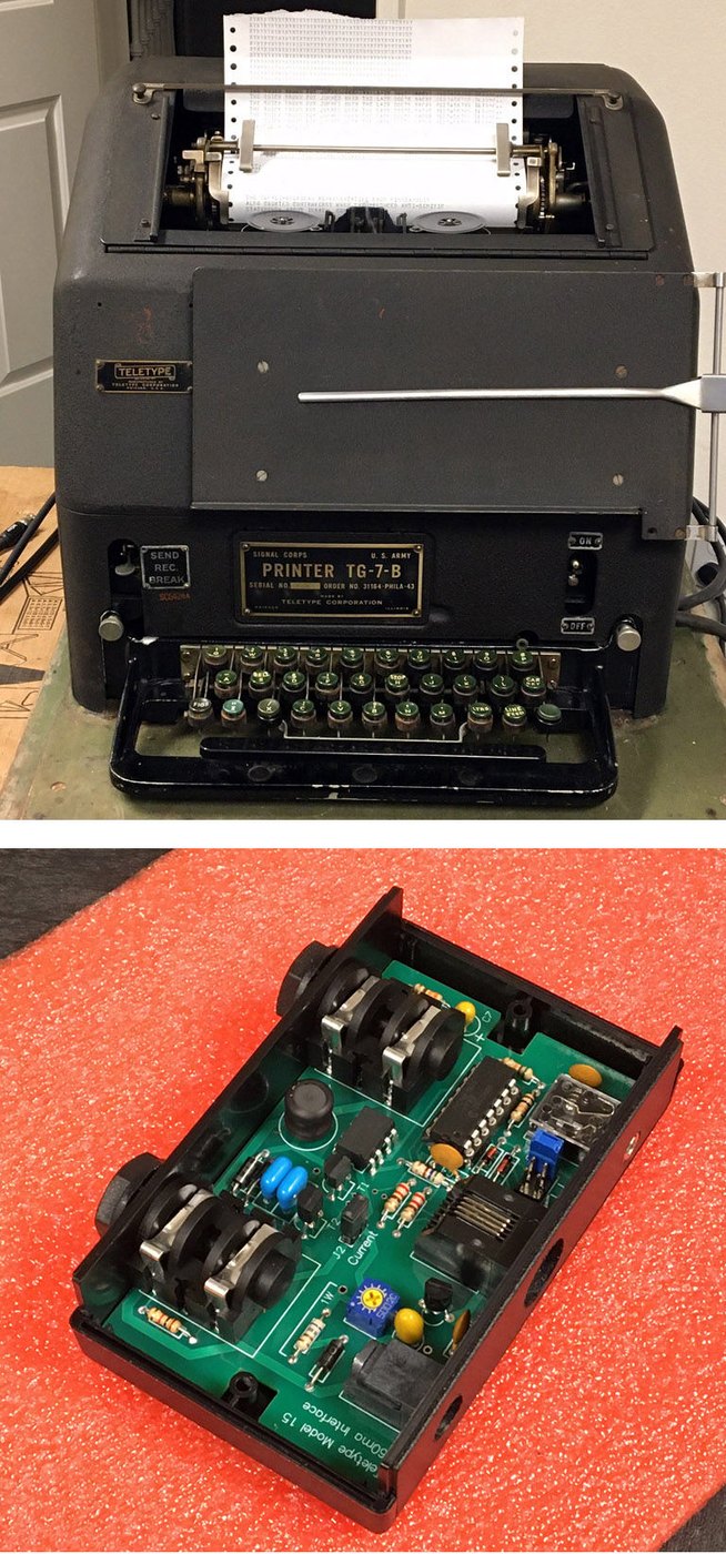
John Nagle’s ttyloopdriver. Nagle’s open-source USB board (GPL-3.0) takes the same idea from the other direction. An isolated boost converter built around an LT3750 capacitor-charging controller charges two 1 µF capacitors to about 120 V during each space. At each mark they are dumped into the magnet, and after a few milliseconds a 15 V sustain supply holds the current, which a depletion-mode MOSFET regulates at 60 mA. The board draws about a watt, all from USB, and its README reports that version 3.3 drives a Model 15 and has been used on a Model 28. Its weak point is parts: it relies on a CP2102 reprogrammed to alias 600 baud to 45, and the CP2102 is “not recommended for new designs”, while the CP2102N “will not work”.
Both boards carry the same warning for some Model 15s. Nagle’s README puts it plainly: some machines have an RF noise-suppression capacitor across the keyboard contacts, and “the capacitor used is large enough to cause typing errors with this board”. The fix is to disconnect it, and the same caution applies to any low-voltage board with a sensitive keyboard input. A big capacitor across the contacts is the 1950s cure for arcing (above); a sensitive modern sense circuit sees it as a slow edge.
Why the one-switch version does not work. A circuit that turns up in forum posts and sketches puts a single MOSFET on the low side of the magnet and a diode from its drain into a “catch” capacitor, on the reasoning that the kickback will charge the capacitor and the capacitor will help the next mark. The first half happens. The second cannot, as drawn: nothing connects the charged capacitor back to the coil when the next mark begins, because the coil’s top end is tied to the supply and the only switch is at the bottom. The energy has nowhere to go, so the capacitor charges higher on every break until a bleeder resistor or a zener burns the energy off, which makes the circuit an ordinary clamp after all. To reuse the energy, something must switch the capacitor across the coil at the start of the mark. In the DeRamp board that is the solid-state relay; in Nagle’s board it is the dump path from the boost capacitors; and in Design B below it is a second MOSFET at the top of the coil.
3.3 Design B: a cool driver — the asymmetric half-bridge
Design B is the build-your-own version of the same idea, arranged the way motor and stepper drivers arrange it. It is a small, cool replacement for the 120 V supply and its 25 W ballast resistor, and it is the one to build if heat or safety is the reason for replacing a classic supply.
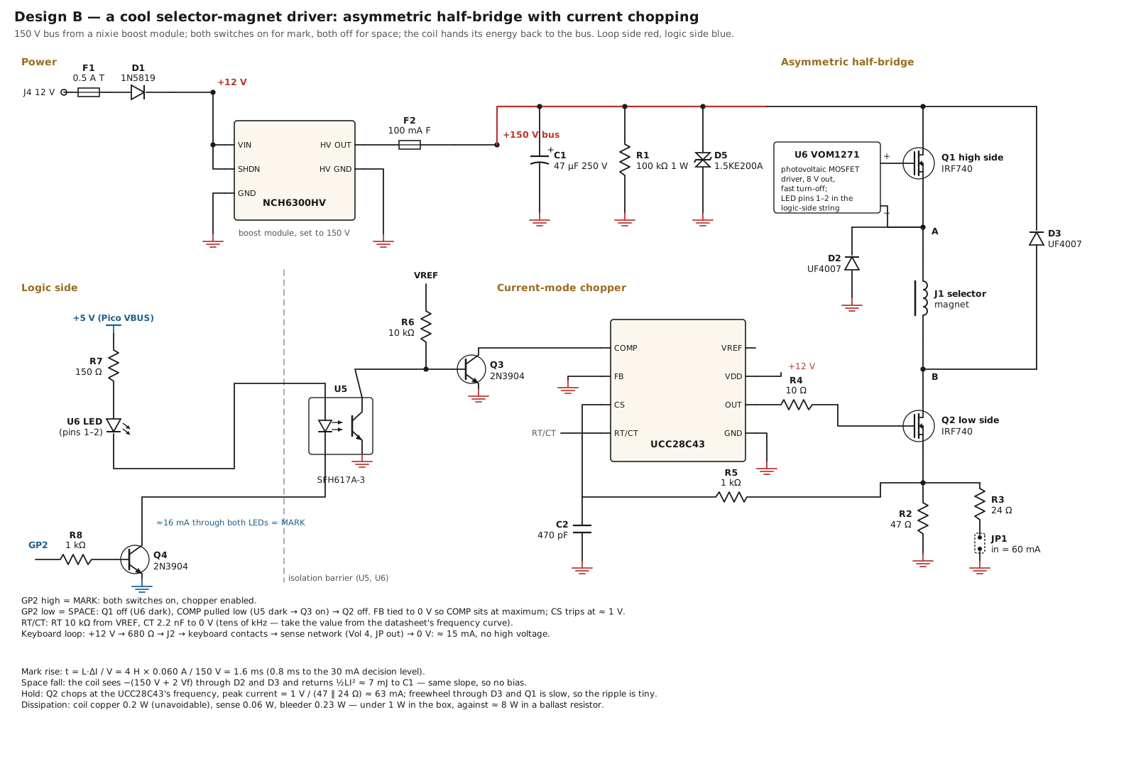
The bridge. Two N-channel MOSFETs, one at each end of the coil, and two fast diodes crossing the other way. That is all an asymmetric half-bridge is.
-
Mark: both switches on. The full bus voltage sits across the coil, and the current rises almost linearly:
t = L x dI / V = 4 H x 0.060 A / 150 V = 1.6 ms to full current
                                        0.8 ms to the 30 mA decision level
with the 4 H figure from Trammell Hudson’s notes (Vol 1).
-
Hold: chop the low side. Once the current reaches its set point, the controller turns Q2 off for a moment. The current then circulates through D3 and Q1, with almost no voltage across the coil, so it decays with the coil’s own 73 ms time constant: in a few tens of microseconds it falls by a few microamperes. Q2 turns back on, the bus tops the current up, and the cycle repeats. The ripple is negligible and nothing gets hot.
-
Space: both switches off. The coil’s current now has only one path: up from ground through D2, through the coil, and through D3 into the bus. The coil sees the whole bus voltage in reverse, so the current falls exactly as fast as it rose, and its stored energy, about 7 mJ, goes back into the 47 µF bus capacitor instead of into a resistor or a zener.
loop_sim.py puts numbers on the symmetry: 0.80 ms from the mark edge to 30 mA, 0.77 ms from the space edge, a bias of −0.1 per cent. It is the fastest and the most symmetrical of the designs in Vol 1’s figure.
The bus: 150 V from a nixie module. A nixie-tube boost module makes a convenient bus: an Omnixie NCH6300HV, for example, runs from 3.7 to 15 V, has an output adjustable from 100 to 230 V, delivers 60 mA typical at 12 V in and 170 V out, and has an SHDN pin that must be pulled high to enable it. The bus hardly loads it. The energy taken at each make comes back at each break, so the module only has to supply the coil’s copper losses, about 0.2 W at 60 mA into 55 Ω. A 47 µF 250 V capacitor (C1) holds the bus; a 7 mJ return raises it by about one volt. A 100 kΩ 1 W bleeder (R1) discharges it when the power is off and absorbs any small surplus, a 1.5KE200A transient suppressor (D5) caps it, and a 100 mA fast fuse (F2) protects the module.
The chopper: a UCC28C43. The low-side switching is ordinary peak-current-mode control, the job a UCC28C43, a current production version of the classic UC3843, was made for. Its CS pin trips at about 1 V, so the sense resistor sets the current:
60 mA:  1 V / (47 ohm || 24 ohm) = 1 V / 15.9 ohm = 63 mA     (JP1 in)
20 mA:  1 V / 47 ohm                          = 21 mA     (JP1 out)
Its output can run near 100 per cent duty cycle, so during the rise it simply holds Q2 on until the current arrives. FB is tied to 0 V so that the error amplifier holds COMP at its maximum, and pulling COMP to ground stops the output. That is how the space command reaches the low side: Q3 holds COMP low unless optocoupler U5 is lit.
The high side: a VOM1271. The high-side MOSFET’s source moves with the coil, so its gate needs a floating drive. A bootstrap driver will not do, because a teletype line idles marking for minutes at a time and a bootstrap capacitor discharges. Vishay’s VOM1271 is a photovoltaic MOSFET driver: an LED and a stack of photodiodes that produce about 8.4 V at 10 mA of LED current, with a built-in fast turn-off. Its datasheet gives a turn-on time of about 53 µs and a turn-off of about 24 µs, a few thousandths of a 22 ms element. It needs no supply on the high side at all, and it is an optocoupler in its own right.
The logic side. One GPIO drives a transistor that lights two LEDs in series, U6’s and U5’s, from the Pico’s 5 V at about 16 mA. GP2 high is mark: both MOSFETs on, chopper enabled. GP2 low is space. If the Pico loses power, the loop goes to space and the machine would run open, which is why the motor relay is controlled from the same Pico: no Pico, no motor.
The keyboard. Split from the selector magnet, the keyboard loop needs no high voltage, as the DeRamp board shows. Design B feeds it from the 12 V input through 680 Ω, about 15 mA, into the same sense network as Vol 4 with its jumper set for 20 mA.
What it dissipates. The coil’s own copper, 0.2 W, which every design pays. The sense resistor, 0.06 W. The bleeder, 0.23 W. The controller and the module’s losses, a few tenths of a watt more. Under a watt in the box, against about 8 W in the ballast of a classic supply and 2.5 W in Design A. There is no heatsink.
The costs. Design B has more parts than Design A, and it has a 150 V bus inside the box, which needs the same respect as any classic loop supply: an enclosure, the bleeder, and a meter check before hands go in. Its controller frequency comes from an RT/CT pair whose value should be taken from the UCC28C43 datasheet’s frequency curve, and its parts are newer and less forgiving of a wrong connection than a resistor. Its reward is a loop that is fast, symmetrical and cold, and that a reader can build from catalogue parts. Vol 8 lists them in the printable BOM. Bring it up the way Vol 2 describes for Design A, with the bus measured and discharged before the first connection.
3.4 Choosing a supply
Table 1 — Choosing a supply
| Approach | Supply voltage | Heat at 60 mA | Edges | Isolation | Notes |
|---|---|---|---|---|---|
| Station rectifier / Navy supply | 120–130 V | 7 W per loop in resistors | fast make, release left to the contacts | transformer | the original; heavy, and often decades past its capacitors |
| Vintage terminal unit’s internal supply (ST-6, ST-5000) | 175 V | ≈10 W | 2N5655 transistor keyer | transformer | period-correct; read the manual completely before connecting anything |
| Hobby transformer and resistor | ≈150 V | ≈9 W | fast make | transformer | the classic; avoid for new work |
| Teletype TP177010 driver (1965) | ≈40 V internal | small | forced rise, controlled discharge | transformer | the right idea, from Teletype itself |
| Design A: 48 V constant-current sink | 48 V | ≈2.5 W | symmetrical by design | the adapter | under the touch-safe limit; simple; no adjustment |
| Design B: asymmetric half-bridge, chopped | 150 V bus from 12 V | under 1 W total | fastest and most symmetrical; energy recovered | adapter + optocouplers | cool and small; more parts; a 150 V bus inside the box |
| DeRamp regenerative interface | 15 V adapter | negligible | regenerative snubber (captured 40–60 V) | the adapter | proven; a complete interface, not just a supply; $20 board |
| ttyloopdriver (John Nagle) | USB, boosted to ≈120 V | ≈1 W from USB | capacitor dump, 15 V sustain | isolated boost | open source; depends on the CP2102’s baud aliasing |
Design A is the basis of the Pico interface in Vol 4 and Vol 8, because it is the simplest thing that works; Design B drops into the same interface in place of block A when a cool, small driver matters more than a short parts list. Either one needs only two things to talk to a computer: a way for the computer to switch the magnet’s current, and a way to see the current in the keyboard loop.
Next: Vol 4, the computer’s side of the loop — sensing it with an optocoupler, keying it with a high-voltage transistor or MOSFET, keeping the computer isolated, and which USB-serial chips can manage five bits at 45 baud.
3.4.1 Sources (Vol 3)
- DeRamp regenerative snubber (“captures 40v-60v … dumped back into the loop”), voltage boost (+20/30/40 V), Baudot pass-through, pulling-magnet 0 Ω / holding-magnet 150 Ω 1 W R2, PIC16F1824, 15 V adapter; parts list (C1/C2 1.0 µF 250 V ceramic, D1–D3 FR104, T1/T2 TN5325N3, U1 LH1505AB-class solid-state relay, L1 100 µH). Mike Douglas, user manual and 60ma Teletype Loop Driver schematic Rev A (April 2022). https://deramp.com/downloads/teletype/Model%2015/loop%20interface%20board/ ; product page https://deramp.com/model15_interface.html
- Video: “Interfacing the Teletype Model 15,” YouTube. https://youtu.be/fLkBb9MuTjE
- ttyloopdriver: LT3750 capacitor-charging boost to about 120 V, 1 µF dump capacitors, 15 V sustain, depletion-mode MOSFET at 60 mA, about 1 W from USB, CP2102 600→45 baud aliasing (CP2102N will not work), v3.3 drives a Model 15, RF-suppression-capacitor warning; GPL-3.0. John Nagle. https://github.com/John-Nagle/ttyloopdriver
- NCH6300HV boost module: 3.7–15 V in, 100–230 V adjustable, 60 mA typical at 12 V in / 170 V out, SHDN high to enable, no reverse-polarity protection. Omnixie datasheet v1.0 (2020). https://media-cdn.elecrow.com/media/qb/tmp/common/file/2023/09/NCH6300HV_Datasheet_EN_v1.0-final_28dece39a6d0c7161d5fbe3bf464494f.pdf
- VOM1271 photovoltaic MOSFET driver: 8.4 V typical open-circuit at 10 mA, turn-on about 53 µs, turn-off about 24 µs, integrated fast turn-off. Vishay, document 83469. https://www.vishay.com/en/product/83469
- UCC28C43: near-100 % duty cycle; frequency from RT/CT curves; current-sense threshold about 1 V (confirm in the electrical characteristics table). Texas Instruments, UCC28C4x datasheet. https://www.ti.com/product/UCC28C43
- UF4007 (1000 V, 1 A ultrafast), 1.5KE200A TVS (171 V standoff): manufacturers’ datasheets. Design B values and arithmetic are this dive’s; simulation in
03-outputs/tools/loop_sim.py. - Station rectifiers, Navy supplies, HAL ST-6/ST-5000, TP177010 and the Design A parts in the comparison table: see Vol 2 sources.
- Cross-links: Making the Parts That No Longer Exist, Vol 2 (DeRamp); The Teletype Model 15, Vol 6 (loop supplies for that machine).