Restoring a Teletype · Volume 2
Restoring a Teletype — Vol 2: First Power, First Loop, First Character
The wiring, the motor, the current loop, and the acceptance test that tells you whether the machine is genuinely well or merely working — taking a range.
2.1 The electrical work you flagged
Volume 1 had you inspect the wiring and then walk away from it. Now deal with it, because this is the part that can hurt you.
Brittle insulation is not cosmetic. The failure mode is a conductor at mains potential shorting to a grounded chassis, and the machine’s frame is a very large piece of grounded metal that you will have both hands on. On a machine that has been stored in a damp shed, assume the worst.
The motor leads are the classic offender — right at the motor case, where heat and oil have been working on them for decades. The repair is straightforward and worth doing properly: cut the damaged leads back to sound insulation close to the motor case, and solder on replacements of appropriate modern cable. One restorer used ordinary IEC power cable for exactly this and the GFCI nuisance tripping stopped immediately. That is the tell, incidentally — a machine that trips a GFCI or RCD is telling you it has leakage to earth, and it is right.
While you are in there:
- Test for continuity from every exposed metal surface to the earth pin. A machine of this vintage should be solidly bonded, and if it isn’t, bond it.
- Run it on a GFCI/RCD during commissioning even after you have fixed the leakage. It costs nothing and it is the difference between a fault and an incident.
- Capacitors. Motor start/run capacitors and any line-bypass capacitors are age-limited parts. A synchronous Model 28 motor unit includes a starting relay and capacitor; old paper or electrolytic capacitors in that role fail short as often as open. Replace on sight — they are cheap and their failure is not.
- Lamps. These machines use lamps for copy illumination and for indicators, and the originals are often unobtainable. Substitution is entirely reasonable: one restorer replaced the cabinet’s two 6.3 V #82 copy lamps with automotive 1004 bulbs (12 V, BA15d base), getting pleasant light at reduced current, and found a GE appliance bulb (T7 envelope, BA15d, 15 W at 120 V) that worked for the 60 V margin indicator with the existing 700 Ω dropping resistor. Get the base and the working voltage right and the rest is taste.
2.2 First power
Turn it by hand first. Every assembly, through its full travel, feeling for anything that binds or grates. If it will not turn freely by hand, it must not be turned by a motor.
Then power up — with the loop disconnected.
It will start hammering. This is normal and it is called running open. With no loop connected there is no current, the line looks permanently spacing, and the selector interprets that as an endless stream of start bits and blank characters. It is alarming the first time and it means everything is basically working: the motor runs, the main shaft turns, the selector trips, the printing bail cycles.
If your machine has a test mode — the Model 28’s is a switch on the LESU, the electrical service unit — use it. Test mode lets you type on the keyboard and watch the printing mechanism respond without any external loop at all, which isolates “is the machine working” from “is my interface working.” That separation will save you a great deal of confusion later.
On a governed motor, this is when you set the speed. Switch on the speed target lamp and adjust the governor’s speed-adjusting wheel until the correct ring of the stroboscopic target appears to stand still (see Inside the Teletype Mechanism, Vol 2). If the speed will not hold, or the target drifts erratically, suspect the governor contacts — they arc and pit in normal service, and they are a maintenance item, not a failure. Clean them, check the spring tension, and confirm the switched resistance is intact before blaming the motor.
2.3 The loop, and why you cannot just plug in a serial cable
Here is the thing that everybody assumes wrongly, so it is worth stating flatly:
🔴 You cannot connect a teleprinter directly to a computer. Not with a serial cable, not with a USB-serial adapter, not with a level shifter. There are three independent incompatibilities and you have to solve all three.
1. It is a current loop, not a voltage interface. The machine signals with the presence or absence of current: 60 mA on classic machines, 20 mA on later ones, at a loop voltage of around 100 V. RS-232 signals with voltage — nominally −12 V for mark, +12 V for space. These are not compatible in any way that a passive adapter can fix.
2. It is Baudot, not ASCII. Five bits, not seven or eight, with LETTERS/FIGURES shift handling. Someone has to translate, and handle the shift state, and decide what to do with ASCII characters that have no Baudot equivalent.
3. It is 45.45 baud. Most USB-serial converters will not go anywhere near that low. It is not a standard rate and the hardware often simply refuses.
The high voltage is not arbitrary, either. The selector magnet is a very inductive load — on the order of 4 henries — and inductance resists change in current. To get the armature to pull in and release fast enough to sample a 22 ms element cleanly you need to force current into and out of that coil quickly, and that takes voltage. The traditional answer is a 100 V supply with series resistors, which works and which dissipates a genuinely uncomfortable amount of heat — around 6 watts in the resistors, all of it wasted.
Your two real options are covered fully in Making the Parts That No Longer Exist, Vol 2, but in summary: a vintage terminal unit (an ST-6, a HAL, an iRL FSK-1000 — but read its manual, these throw stout voltages around and misconfiguring one can damage the machine or you), or a modern purpose-built interface board such as the DeRamp Model 15 loop interface, which does the whole job — ASCII↔Baudot, baud conversion, AFSK demodulation, and loop drive — from a 15 V wall adapter.
Wiring practicalities. Loop connections on these machines commonly use 1/4” phone jacks — tip/sleeve or tip/ring/sleeve — which is convenient, because musical-instrument cables are still made by the mile. Note that the printer loop and the keyboard loop may need to be wired separately (full duplex) rather than in series, depending on your interface; the DeRamp board requires exactly that and provides a half-duplex option for local echo instead.
2.4 Taking a range: the acceptance test
The machine prints. You are not finished, because “it prints” and “it is well” are different statements, and there is a single measurement that distinguishes them.
Take a range. The procedure, from Inside the Teletype Mechanism Vol 1:
- Send the machine a continuous stream of test text — RYRYRY is traditional because R and Y alternate the code bits maximally, and “THE QUICK BROWN FOX JUMPS OVER THE LAZY DOG 1234567890” exercises every character.
- Move the range finder down until errors appear. Record that number.
- Move it up until errors appear again. Record that.
- Set it midway between them.
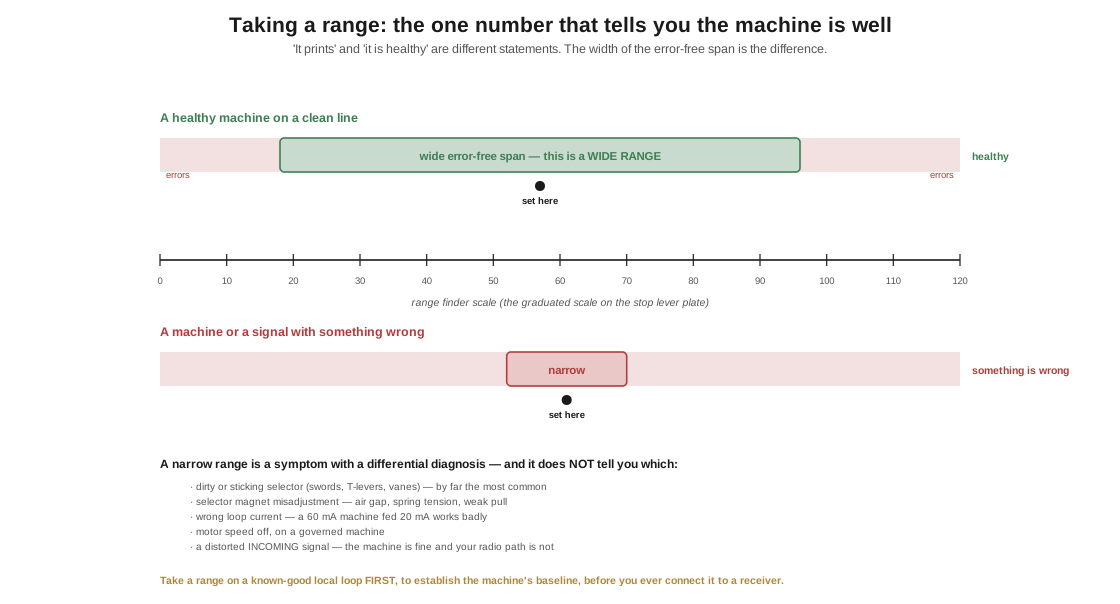
The span between those two limits is the range, and it is a health measurement:
Table 1 — The span between those two limits is the range, and it is a health measurement
| Range | What it means |
|---|---|
| Wide (many tens of points) | The machine is well and the signal is clean |
| Narrow | Something is wrong — and the range does not tell you what |
| Asymmetric or drifting | Timing or speed problem; suspect the motor/governor or the signal source |
A narrow range is a symptom with a differential diagnosis, and it is worth knowing the list:
- Dirty or sticking selector mechanism — the swords, T-levers, or vanes not moving freely. By far the most common cause, and the reason cleaning comes before adjusting.
- Selector magnet misadjustment — armature air gap, spring tension, or the magnet not developing full pull.
- Wrong loop current. A 60 mA machine fed 20 mA will work, badly, with a narrow range. Measure it.
- Motor speed off, on a governed machine.
- A distorted incoming signal, in which case the machine is fine and your interface or your radio path is not.
That last one matters for anyone running RTTY off the air: on a marginal HF signal, the range narrows because the signal is distorted, not the machine. Learning the difference between “my machine is sick” and “the band is bad” is exactly what a range measurement gives you, and it is why a restorer takes a range on a known-good local loop first, establishing the machine’s baseline, before ever connecting it to a receiver.
Retake the range after any adjustment. It is the single number that tells you whether you made things better or worse, and a restoration log that records the range at each stage is worth keeping.
2.5 Patience is the actual technique
One restorer’s Model 28 had a single broken part, and it took a few weeks to find — reading documentation, tracing how each mechanism related to the next, manipulating parts by hand to understand what they were for, and asking Greenkeys for direction. His conclusion is the right note to end on: the hunt was worth it, because it forced him to understand the machine mechanically in a way that nothing else would have.
That is the honest character of this work. It is not difficult in the way electronics repair is difficult — there is nothing invisible, no signal you cannot see, no component whose failure is undetectable. Everything in a teletype is right there in front of you, moving. It is difficult only in the sense that there is a great deal of it and it must be understood rather than guessed at. Be methodical, read the bulletin, and when you are stuck, ask the people who have been fixing these since before I was listening to one in my father’s shack.
2.5.1 Sources (Vol 2)
- 🔴 Principal source: David Stickelman, “Getting started with a teletype, my consolidated notes on restoration” (23 Feb 2025) — powering up disconnected and “running open”; the LESU test switch; the broken-part hunt taking weeks and being worth it; and the interfacing summary, including W6IWI’s explanation quoted there: “Teletype stuff uses a current loop (normally 60 ma, but sometimes 20 mA) at a voltage of about 100 volts … that’s different from RS232 which is a voltage (typically −12V for Mark, +12V for space) … computers normally work with ASCII (7 bit characters) instead of Baudot (5 bit characters) … most USB to serial converters will not go down to 45.45 bits per second.” Also the tip/sleeve and TRS cabling, vintage terminal units (ST-6, HAL, iRL FSK-1000) and their voltage hazards, and the DeRamp interface. http://stickelman.net/index.php/2025/02/23/getting-started-with-a-teletype-my-consolidated-notes-on-restoration/
- Motor lead repair, capacitors, and lamp substitutions — brittle oil-saturated motor leads shorting to chassis and tripping a GFCI, repaired by soldering on replacement line-cord wire; the Model 28 synchronous motor unit’s starting relay and capacitor; two 6.3 V #82 copy lamps replaced with automotive 1004 (12 V, BA15d), and a GE T7 BA15d 15 W/120 V appliance bulb substituted for the 60 V margin indicator behind its existing 700 Ω resistor. kb8ojh.net, “Teletype Model 28 KSR.” https://kb8ojh.net/station/teletype/
- Selector magnet inductance (~4 H) and the traditional 100 VDC supply with current-limiting resistors dissipating roughly 6 W — Trammell Hudson, “Model 15 Teletype.” https://trmm.net/Model_15_Teletype/
- Range finder and orientation procedure — Teletype Corporation / BSP, Description of Teletype Model 15 Teletypewriter, Section P70.013; see Inside the Teletype Mechanism, Vol 1 for the mechanism.
- Governor contacts, speed target and speed adjusting wheel — same primary source; see Inside the Teletype Mechanism, Vol 2.
- ⚠ Safety: this volume involves mains wiring on grounded metal machinery and loop supplies at around 100 V. The advice here is a restorer’s summary, not a substitute for competence with mains work. If you are not comfortable with it, get someone who is.
- Cross-links: Making the Parts That No Longer Exist (interfaces, consumables, and everything you cannot buy); RTTY on the Air (feeding the machine off the air); Inside the Teletype Mechanism.